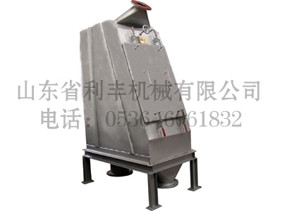
The pulping process cannot get away the pulp concentration while the fiber recovery of waste water also is the concentration process of pulp. The available pulp concentration equipment such as the round mesh thickener, side pressure thickener and various fiber recovery machines, has complex structure, occupies large floor area and requires external power driving. While this machine is designed by improving the introduced like products and suitable for various pulp concentration washing and paper waste fiber recovery. As the newest generation product, it has the advantages of simple structure, small floor area, high processing capacity and little power consumption.
Ⅱ. Working Principle
The pulp delivered under a certain pressure first passes the pulp inlet on the sieve bend top to flow into the pulp distributing plate, where the pulp is accelerated and then flows to the arc filtration zone in tangential direction. In this zone, the pulp is subjected to the action of centrifugal force and repeated dewatering and then enters the outlet under the gravity action to discharge. The filtrated waste water is discharged through the waste water outlet.
Ⅲ. Main Specifications and Parameters
|
Specification/Model Parameter |
HS-1 |
HS-2 |
HS-3 |
HS-4 |
|
|
Dewatering area (m2) |
1 |
2 |
3 |
4 |
|
|
Pulp concentration |
Production capacity T/D |
20-40 |
40-80 |
60-120 |
80-160 |
|
Concentration of Feeding Pulp % |
0.5-3 |
||||
|
Concentration of Outgoing Pulp % |
3-6 |
||||
|
Waste water fiber recovery |
Processing capacity (m3/h) |
100-200 |
200-400 |
300-600 |
400-800 |
|
Concentration of Outgoing Pulp % |
1.5-3 |
||||
|
Pulp (water) inlet pressure (MPa) |
≥0.25 |
||||
|
Water spraying pressure (MPa) |
≥0.15 |
||||
|
Pulp inlet flange |
DN150×1 |
DN150×2 |
DN150×3 |
DN150×4 |
|
|
Pulp outlet flange |
DN200 |
DN200×2 |
DN200×3 |
DN200×4 |
|
|
External dimension (L×W×H) mm |
906×1496×2356 |
1664×1496×2356 |
2416×1496×2356 |
3174×1496×2356 |
|


